Wednesday, September 23, 2015

Fishtanks and the Pi - Part 1 - using Nagios for temperature monitoring

OK, so it's been quite a while since my last post, but I've not been idle, just not really concentrating on all things Pi for some time.  Not least, the Pi 2 has now come out, and in my opinion made the thing infinitely more useful!

My house now consists of two Pi devices in constant use:
  • Monitoring - I use a Pi running Nagios (more of that later!) to monitor my NAS and other services at home.
  • TV recording - I have a Pi running Tvheadend to record DVB-T via a cheap, simple Sandberg DVB-T USB tuner.
Remember back in my first post I said I'd be doing some fish tank automation?  Well, I've finally got around to putting the necessary things together, and after thinking through how to do temperature monitoring I decided that the best solution was to use the very powerful Nagios monitoring platform which I already have in the house, just move the Pi running the platform downstairs to be near the fish tank and write some scripts to make the temperature sensors work.

Now, it seems like a pretty trivial requirement, but I wanted a number of temperature sensors in the tank as I've been nervous for a while about how well the water mixes thermally, especially when I change the water or the house is colder than usual in the winter months.

In order to get this integration with Nagios working, I had to achieve a few other things first, namely:
  1. Find an appropriate, saltwater safe and heavy duty temperature sensor/probe which would work with the Pi.
  2. Work out how to connect a number of them up and avoid any risk of water damaging the electronics!
  3. Get them talking to the Pi.
  4. Get them integrated into Nagios.
  5. Provide time series logging.
In addition, I want to integrate this with a display at some point in the future - more on that later!

Choosing the temperature sensor

So, this was easier than I thought in fact.  The DS18B20 is a very robust 3-pin transistor-cased temperature sensor with a decent temperature range and 0.5°C accuracy.  You can buy versions of these sensors ready wired in a metal tube filled with potting compound, which should be pretty resistant to the salt water (and inert).  I bought these and found they worked really well for this purpose.  Time will tell in terms of how well they react to the salt (and the livestock react to them, though I think it'll be fine!).

Connecting the sensors together

The 1-wire protocol makes the sensors very easy to wire up - they basically have a single signal line, and require 0v and 5v supplies.  The can operate with 'parasitic power' - as shown in the datasheet, but as this requires additional components, and the Pi has a readily available 5v power supply, I thought it wasn't worth the trouble.

The real bonus with these devices is that you can connect as many of them as you like together in parallel.  This means that wiring becomes trivial.  I opted for a simple stripboard for this project, pretty quick and easy to wire together and designed for lots of parallel connections!

Sensors connected together using stripboard
The picture to the right shows the completed stripboard with the wires cable tied to it for strain relief.  You'll also note I've put a BPM180 PCB on the board as well - this is a different type of temperature sensor which I've included to use as a calibration check to ensure the DS18B20s are behaving.  More on making that work in a later post.  The labels are the identified serial numbers of the sensors.  I kind of jumped the gun here and did things backwards - I suggest you do as well (this isn't meant as a how-to article, just as advice!) - connect the sensors one at a time to the Pi and record the serial numbers generated in the /sys/bus/w1/devices directory so you know which one is which later on!

I've added a 3-pin header at the far end so that I can extend this board to even more devices; I intend to put one through a hole in the wall to measure the outside temperature, for example.

The grey multi-core cable at the bottom of the picture is a 6-core cable going to the Pi.  This has 3 connections (black, red and green) going to the 1-wire sensors, and the other 3 going to the BPM180 (with another 0v black line!) - annoyingly the BPM180 uses 3.3v, not 5v so there are two power lines for these two types of sensor.

You'll see I've used a liberal amount of heatshrink sleeving - this is highly recommended as not only does it keep the strands of wire / soldering from shorting between pins, but it also makes the thin wires less susceptible to breaking off as it reduces the likelihood of any right-angle bends in the wires.  You can buy it from any good electronics store, and a hairdryer or any gas powered soldering iron with heat gun attachment (my preference) will get the things to shrink.  At some point, I'll probably protect the whole thing with some larger heatshrink, but for now I've left it unclothed as I want to keep it accessible for debugging.

On the other end of the grey cable is the Pi itself, I've soldered additional headers onto the Adafruit 16x2 LCD display (ready for Part 2 of this project!) and soldered the wires from the cable onto those headers with additional heatshrink.

Interfacing with the sensors

The 1-wire protocol makes interfacing with the sensors pretty easy, but I did battle with a software update to the Pi breaking things for a while about 6 months ago.  Basically, Raspbian made the move to Device Tree (DT) at that point, which dynamically creates device files in /sys and /dev to ensure interoperability with all of the hardware ecosystem which has taken off massively over the past year or so.  You can read more about Device Tree here on the Raspberry Pi website.

What the DT update meant was that you now have to specify the 1-wire settings in /boot/config.txt as well as loading kernel modules:

dtparam=i2c_arm=on
dtoverlay=w1-gpio,gpiopin=4

Once you've made this change to config.txt, for me it just worked and the relevant kernel modules were automatically.  Some documentation does talk about enabling w1-gpio and w1-therm manually in /etc/modules, but I think this was written prior to DT being enabled.

Anyway, once this is all done, take a look in /sys/bus/w1/devices/.  If the sensors are connected and the module is loaded properly, you should see something like this:

As you can see, there are a bunch of hex-coded folder links, and a 'bus_master' folder.  It's the hex-coded names we're interested in.  These are the serial numbers of the connected sensors.  A peek in one of these folders shows a few files, and the one we care about - cryptically named w1_slave:

The w1_slave file contains - if the sensor is working correctly - the measured temperature, along with some checksum data and a 'YES/NO' field.
The fact that this file shows YES means that the checksum is accurate (there was no data loss in the wire, and the sensor didn't fail somehow) and so you can believe the temperature data.  If there was a NO in this field then we shouldn't trust the rest of the data in the file.

In case you're wondering where the temperature is, look at the 't=' number; familiar?  Yep, that's it - the sensor provides a number in millidegrees, so you need to divide by 1,000 to make sense of the number.  Remember me mentioning above that the accuracy is only 0.5°C - yeah, I'm not sure why the number needs to be that accurate either, but there we go.  You get 3 decimal places, but you can't believe them.

Integration with Nagios

Now it's all very well getting the data, but what are we going to do with it?  Well, we need to parse these files and then present the data in a form that Nagios can deal with.  Fortunately, thanks to Rule 21 of The Internet (I think that's the right rule, and no, I don't mean 34), someone has already written a nice Python library to parse this data - they are using the same sensors for brewing beer - good luck to them, I may try it myself at some point!.  Anyway, after pouring myself a pint I forked their snippet and made a few changes to better suit my needs in the Nagios integration, the code is available here on BitBucket.

Now for the Nagios plugin.  I won't go into lots of detail in the blog post, hopefully I'll get around to further documenting the code soon but it's still pretty self explanatory - go ahead and take a look here / clone the repo: https://bitbucket.org/cscashby/nagios-check-ds18b20There's one thing that probably warrants further information; I have combined maximum and minimum checks into the same call to check_ds18b20.py - this is primarily for compactness within the Nagios config, but also for a pretty good reason, which is that the file reading actually can take some time (for the sensor to stabilise and write the data to the file), so it's best not to read it twice if you can avoid it.  Therefore there are both -w and -W, -c and -C parameters (for warning min/max and critical min/max respectively) to the check script.  This may well break Nagios guidelines, but hey, it works for me!

[UPDATE 1-OCT-2015] I'd missed a cunning feature in Nagios - you can specify max and min thresholds as ranges - this page from the plugin development guidelines outlines the solution.  I've checked in a change to the repo to do just this, thus removing the -C and -W parameters.

Installation is pretty easy, put the check_ds18b20.py and temp.py in a folder somewhere, make it executable by the nagios user and set up your configuration files appropriately.

One thing you do need to think about is what 'host' to put the service checks in.  It doesn't really make sense to ping a host for temperature, so I created a quick check_forceok command which can be used in a host check to always return OK and keep Nagios happy.  That's also in the repo for your use.

My fishtank monitoring config files (the relevant bits - I've omitted the rest of my setup) are in the repo as an example file.  Run check_ds18b20.py without any parameters to get the help text and get some advice on parameters, etc.


Time series data logging

This turned out to be the main thing which pursudaded me to use Nagios in the first place; although I could drop the data into rrdtool or similar, why not kill two birds with one stone and combine the aggregate time series data with the rest of my system monitoring?

Nagios (since version 3) has provided the ability to store performance data alongside the service and host checks, and via an add-on it is pretty simple to graph this stored data.  I chose to use nagiosgraph for this, but there are many others.  The specifics of the graphing solution are outside the scope of this article, but suffice it to say that it's pretty easy.  This is where the Pi 2 really comes into its own.  I tried installing graphing solutions using the original incarnation and producing a lot of graphs was frankly beyond the capabilities of the limited RAM of those older machines.

Sunday, January 6, 2013

Remote accessing the Pi with Synergy

If, like me you have a Raspberry Pi on your computer desk, and want to connect to it and hack around, it's a pain to have two keyboards / mice on your desk, and keep typing on the wrong one, etc.

There is a solution to this!  A simple app called 'Synergy' which is available on Windows, Mac and Linux, which basically makes one/many 'client' machines an extension of the 'server' screen real-estate.

It's trivial to install, download it, run it, and add the pi (or other machine) to the right, left, top or bottom of the screen in the server settings box.  Click start, make a note of the IP address that it's configured to run on, and you're ready to accept connections.

On the Pi, install the software:

sudo apt-get update  # get the latest version of software catalogue
sudo apt-get install synergy

And run it:

synergyc {IP of server}

Move the mouse to the chosen side of the screen and it appears on the Pi.  When you have done so, the keyboard is also attached virtually to the Pi - magic!

Saturday, October 20, 2012

Building the Gertboard

I got my hands on a Gertboard the other day, and decided I would document the creation of it.

The first thing I saw when I opened the bags of kit were the SMD components - which scared me somewhat - having done a lot of soldering before but never with surface mount.  Still, the assembly manual included some good advice, and I wasn't too nervous about soldering them.

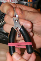
Elastic band around pliers to make life easier
Look! No Hands!
I went through the parts list, and realised that none of the SMD resistors or capacitors had their values on them, so had to look up all of the part codes on the Farnell website.  Not a big deal, but a bit of a pain, and beginners may get confused by having to do this...

Then I set off.  The advice on soldering SMD in the manual is very well written, and I had no issues when I followed it pretty much to the letter, despite not having decent tweezers, and having to find a couple of errant resistors which had pinged across the desk on a few occasions!

Firstly, a couple of tips.  As you can see in the picture to the right, I tightened an elastic band around my pliers to hold them together - this makes holding things in them a hands free operation, and make life a lot easier!  I also pre-soldered one of the two pads for all of the SMD devices, which meant I could easily identify them and could spend more time concentrating on the fiddly bits.

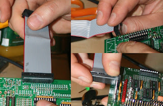
Using the IDC connector to keep header pins straight
Using the IDC connector to keep pins aligned
Secondly, the tip in the assembly manual which recommends using a sponge to keep the components flush with the board is a really good idea for the components, but it doesn't help keep the headers aligned.  I did this by using the ribbon cable IDC connector - also pictured, to ensure that the headers had the right spacing.  I could even use it for the long headers by using it at 90 degrees to the normal direction - between the joins between the sections of header.

All in all, the assembly went pretty smoothly, and (as I didn't have my multimeter to hand) I decided to risk it and went ahead and powered the board up straight away - without testing voltages, etc - I wouldn't recommend this, but I got lucky and it worked first time - I only checked with the button demo, I'll be playing with it more over the next few weeks / months.
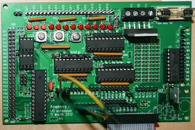
Completed, connected gertboard with jumpers ready for the button.c test program
The completed board, wired for the button test
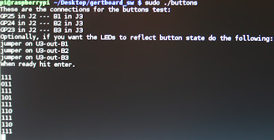
Running the buttons test on screen with the output shown
The button test running on the pi (sorry for the quality of this one!)
Finally, if you've held on for this long, here's a 1 minute rendition of me building the thing in stop motion...


Monday, October 15, 2012

Long time no blog!

Sorry for the long silence; I've been mentally busy at work, etc.

There's been a lot that has changed since I've been quiet; The Raspberry Pi is available at other stores (Maplin, CPC), has twice as much RAMRaspian is the new recommended image (and it's great, I love the automatic configurator that starts on first boot!), and Eben's released books 'Beginning Raspberry Pi' and 'Raspberry Pi User Guide'.  There's certainly some amazing stuff going on!

Anyway, my media centre project is going well.  I opted for Raspbmc for my RasPi media centre over OpenElec in the end (I'll post in more detail about this later), and it's working great!  I'll post soon about that, as well.  On the downside, I've had issues with my chosen USB Satellite decoder, it seems to be much more susceptible to slightly poor satellite signals compared with the PCI one I have in my Linux desktop, so I've switched back to that for now running TVHeadend.  When I get around to it I'll try the USB decoder/RasPi combo in a different place with a known good satellite signal.  If that works, I'll get a man in to repoint my dish! - I'm still hopeful that I can make something work with this.

In the meantime, I've consolidated my files, and got the Pi working as an Apple Time Machine server, which works really well - I'll be blogging about that shortly.  My intention is to take a Pi and an external HDD to a friend's house, when I'm there (on their Wi-Fi) my Mac will automatically back up to the Pi, and for only £ 25 more than the cost of the drive.

Also, my Gertboard arrives soon.  Hopefully I'll be able to work out how IO works properly then and put some more blog posts up.  Given time!

Monday, June 4, 2012

Building kernel modules

The Raspberry Pi is a very capable little machine, and there is support for common hardware devices provided out-of-the-box. However, you may come across a device that isn't supported, and need to build kernel modules to support it. This is remarkably simple once you get the right bits and pieces on your pi's filesystem, and quite a few people have produced how tos. Perhaps the most useful, and the one I've used to produce this guide is the one writte by Mchr3k on his blog in the article: 'Raspberry Pi Progress'. I've put my own steps below, but it is mainly based on his guide - thanks Mchr3k!

These instructions are tested on a clean install of debian straight from the Raspberry Pi website (I used version debian6-19-04-2012.zip), but you do need more than the default partition size, so resize the partition first (there's a useful guide here until I get around to writing one!).

We already have the build-essential package provided with the Pi which takes care of most of the compilation, but we need git to get the repository, libncurses5-dev to run the configuration menu and the command bc for the kernel build (not in build-essential).

sudo apt-get install git libncurses5-dev bc

Download the kernel sources from the Raspberry Pi source control repository, then link them to the kernel directory - I use a symlink here as means I can store the files on a larger filesystem (I have a USB attached drive)

git clone --depth 1 https://github.com/raspberrypi/linux.git
sudo ln -s `pwd`/linux /lib/modules/3.1.9+/build

Then, we get ready to do the kernel build. The Pi stores the current kernel configuration in the /proc/ filesystem, so we can use that to provide an initial setup - all these commands need to be done from the ~/linux directory.

gzip -dc /proc/config.gz > .config

Set up your new kernel, setting what you need to [M] in the configuration.

make menuconfig

Set up the building process, and start the build - NOTE you have to build the entire kernel the first time to ensure that the symbols are synchronised - the kernel doesn't need to be used for the modules to work (and if you want to add more modules in future, you can just do make modules) - does anyone know how to avoid having to do this?

make

Go and have a lot of coffee - this step takes a significant amount of time - like, about 6 hours!

Once this is done, and if you have any build errors, let me know, I may be able to point you in the right direction, we can now go ahead and install the modules:

sudo make modules_install

If the drivers you require also have firmware, then install that, too:

sudo make firmware_install

All done - congratulations!

What do you use your Pi for?

So I posted a poll a while ago, and although I didn't get many results, it seems people are quite interested in media using the RasPi...  I'm going to re-open the poll and post the results here.  I'm going to keep posting on a few topics, but will certainly be looking at the media use for the 'Pi.  I've got an OpenElec build running as my primary media source at home now, so will comment on this quite a bit over the coming weeks.

Education / teaching
  1 (7%)
Media
  6 (46%)
Something server (storage, etc)
  3 (23%)
Something hardware (measurements, automation)
  3 (23%)

Tuesday, May 22, 2012

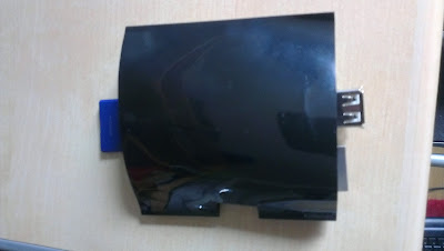
Unconventional case

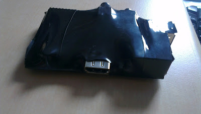
So I decided to make a really simple case...

It involves 83mm heat shrink, which you can buy here, and a hot air gun.

  • Cut to size, about 10mm or so outside the edges of the board
  • Cut a slot out for the HDMI connectors (or audio / composite if you're so inclined)
  • Apply hot air carefully so as to not distort the tubing around the HDMI cable
The result: A fairly well protected Pi that can work on a metal surface without shorting things...  It's not pretty, I grant you.

Pictures here (I failed to cut the tubing long enough so ended up layering a second one on: